What is a capacitor?
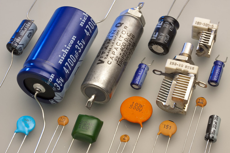
A capacitor is a circuit component which stores electric potential energy. It is made up of two parallel plates: a positive plate and a negative plate. An insulator is inserted in between the plates to ensure that electrons cannot flow between the plates. The two plates have opposite charges, and the charge of a capacitor refers to the charge of its positive plate. Charge is measured in coulombs and represented using the symbol \(Q\).
How does a capacitor work?
A capacitor is charged by connecting it to a voltage source such as a battery. The positive plate gets charged with a charge of \(Q\), and the negative plate gets charged with a charge of \(-Q\). The charge \(Q\) is proportional to the voltage \(V\) which is applied across the capacitor: \[Q=CV\] The proportionality constant \(C\) is known as the capacitor’s capacitance. Capacitance is measured in farads, where 1 farad is equal to 1 coulomb per volt.
What are some applications of capacitors?
Capacitors are used to temporarily store energy, similar to small batteries. But unlike batteries, it can be charged and discharged rapidly, while having much less capacity. Due to its properties it is used in almost all electrical circuits. The following are some of the applications of capacitors:
Capacitors in Camera Flashes
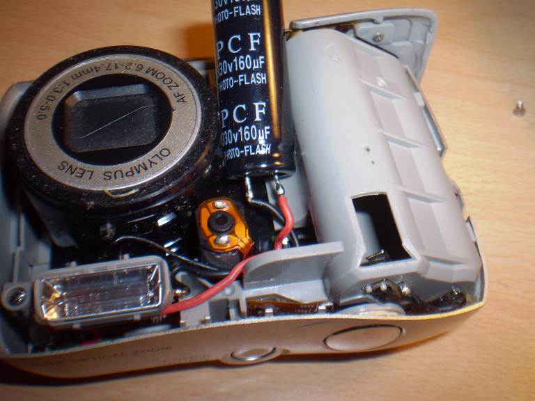
Typical portable cameras are powered by \(1.5V\) batteries, which is not enough to power the camera flash that briefly turns on when the user presses the shutter button. To power the flash, a step-up circuit is used to bring the voltage of the power supplied by the battery up to around \(200V\) and the capacitor in the camera is charged to a high voltage using the power. When the user presses on the shutter button, the capacitor is discharged instantly through the flash bulb, which produces a bright flash of light.
Capacitors in Electric Buses
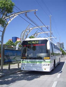
One possible application of capacitors are in electric buses. A typical capacitor’s capacity would not be enough to power a bus, but a new form of capacitor, called ultracapacitors, has a much higher energy density, and is suitable for running a bus. Using a capacitor instead of a battery comes with a number of advantages such as less overall maintenance required, as batteries lose capacity after a certain amount of charging cycle. Capacitors also charge and discharge much quicker.
The driving pattern of buses is very different from cars, as buses tend to stop and start frequently. This means that the bus could be charged at bus stops every few kilometres, but it must be done very quickly. An ultracapacitor is suitable for this application, as it can be charged and discharged very quickly. The bus would be charged using induction coils under the road at each stop.
Finally, the use of capacitors would be more environmentally friendly compared to using batteries. Capacitors use less toxic materials compared to conventional Lithium-ion batteries. These batteries make use of rare earth metals such as cobalt, which are mined in countries where the mining process is often done in an unethical manner.
Storing Energy inside a Capacitor
Let us imagine a capacitor with a capacitance of \(C\), which a charge of \(+q\) on one plate and a charge of \(-q\) on the other. Then the potential difference between these plates are then \(V = \frac{q}{C}\) as explained above.
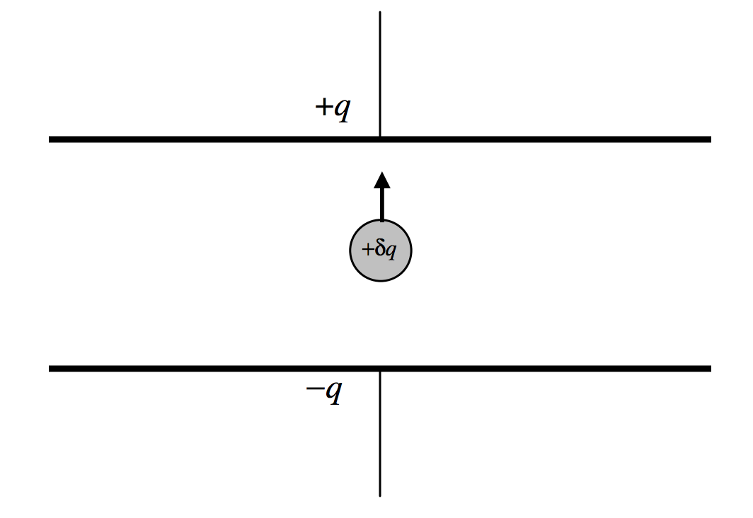
Let us now attempt to move a charge of \(+dq\) from the negative plate to the positive. Increasing the charge on the plates by \(dq\) increases work stored by the capacitor by \(dW\). From \(W = V \times Q\), we can see that the work required to move this charge is \(dW = V(q)dq = \frac{q}{C} dq\).
As we keep transferring charge, the total work stored in the capacitor increases. The rate of this increase is \(\frac{dW}{dq} = \frac{q}{C}\), which is the same as the potential difference across the plates. To find the total work stored, we isolate \(W\) and integrate from \(q = 0\) to \(q = Q\):
\[ \int_0^Q dW = \int_0^Q \frac{q}{C} dq \] \[ W = \frac{q^2}{2C} \]
From \(Q = CV\), we can rewrite this as:
\[ W = \frac{CV^2}{2} \]
Discharging a capacitor
When a charged capacitor with a capacitance of \(C\) and an initial charge of \(Q_0\) is connected in a circuit to a resistor with a resistance of \(R\), charges will flow from the capacitor’s positive plate, through the resistor, to the capacitor’s negative plate. During this discharging process, the capacitor’s electric potential energy is converted into internal energy by the resistor.
In this section, we will find a formula for the capacitor’s charge \(Q\) in terms of the time \(t\).
Below is a simulation which demonstrates a capacitor being discharged through a resistor (each blue dot represents a negative charge, and each red dot represents a positive charge):
Creating a differential equation
There are 3 facts about the circuit which we know:
- The current \(I\) in the circuit is the rate at which the capacitor’s charge \(Q\) decreases, so \[I = -\frac{dQ}{dt}\]
- Due to Ohm’s Law, the current \(I\) and the voltage \(V\) are related by the resistor’s resistance \(R\): \[I=\frac{V}{R}\]
- The voltage \(V\) and the charge \(Q\) are related by the capacitor’s capacitance \(C\): \[Q=CV\]
Combining the 3 equations above, we can produce a differential equation relating the charge \(Q\) to the time \(t\): \[-\frac{dQ}{dt}=\frac{Q}{RC}\]
Solving the differential equation
Now, we will solve the differential equation in order to express \(Q\) in terms of \(t\).
First, we separate the variables: \[\frac{dQ}{Q}=-\frac{dt}{RC}\]
Next, we integrate both sides: \[\int\frac{dQ}{Q}=\int-\frac{dt}{RC}\] \[\ln Q=-\frac{t}{RC}+X\] \[Q=e^X \cdot e^{-\frac{t}{RC}}\] where \(X\) is a constant.
Initially, when \(t=0\), the capacitor’s charge \(Q\) is equal to \(Q_0\). This implies that \(e^X=Q_0\). Therefore, we now have a formula expressing \(Q\) in terms of \(t\): \[Q=Q_0 \cdot e^{-\frac{t}{RC}}\]
This shows that when a capacitor is discharged through a resistor, its charge decays exponentially. You can see this happening in the simulation which was shown at the beginning of this section.
Challenge problem
Here is a challenge problem to test your knowledge of the application of calculus to capacitors:
A variable resistor is a resistor whose resistance changes over time. Suppose that we have a variable resistor with a resistance satisfying the function \(R=R_0+kt\), where \(R_0\) and \(k\) are both constants, and \(t\) represents the time. \(R_0\) (measured in ohms) is the initial resistance, and \(k\) (measured in ohms per second) is the rate at which the resistance changes.
Now, a capacitor with a capacitance of \(C\) and an initial charge of \(Q_0\) is discharged through this variable resistor. Find an expression for the capacitor’s charge \(Q\) in terms of the time \(t\).
Click here to reveal the solution (after you have attempted to solve the problem!)
We can start by copying the differential equation from the Creating a differential equation section, except with \(R\) replaced with \(R_0+kt\) (the variable resistance):
\[-\frac{dQ}{dt}=\frac{Q}{(R_0+kt) \cdot C}\]
To solve this differential equation, we isolate the variables and then integrate both sides: \[\int -\frac{dQ}{Q}=\int \frac{dt}{(R_0+kt) \cdot C}\] \[-\int \frac{1}{Q}dq=\frac{1}{R_0C}\int \frac{1}{1+\frac{k}{R_0}t}dt\] \[-\ln Q=\frac{1}{R_0C}\cdot\ln\left(1+\frac{kt}{R_0}\right)\cdot\frac{R_0}{k}+X\] \[\ln Q=-\frac{1}{kC}\cdot\ln\left(1+\frac{kt}{R_0}\right)-X\] \[Q=e^{-X}\cdot\left(1+\frac{kt}{R_0}\right)^{-\frac{1}{kC}}\] where \(X\) is a constant.
We know that \(Q=Q_0\) when \(t=0\), so \(e^{-X}=Q_0\). Therefore, we now have a formula expressing \(Q\) in terms of \(t\):
\[Q=Q_0\cdot\left(1+\frac{kt}{R_0}\right)^{-\frac{1}{kC}}\]